25 circuits
From an LED and its resistor to a microcontroller. Each one has a breadboard you can touch.
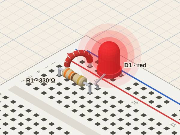
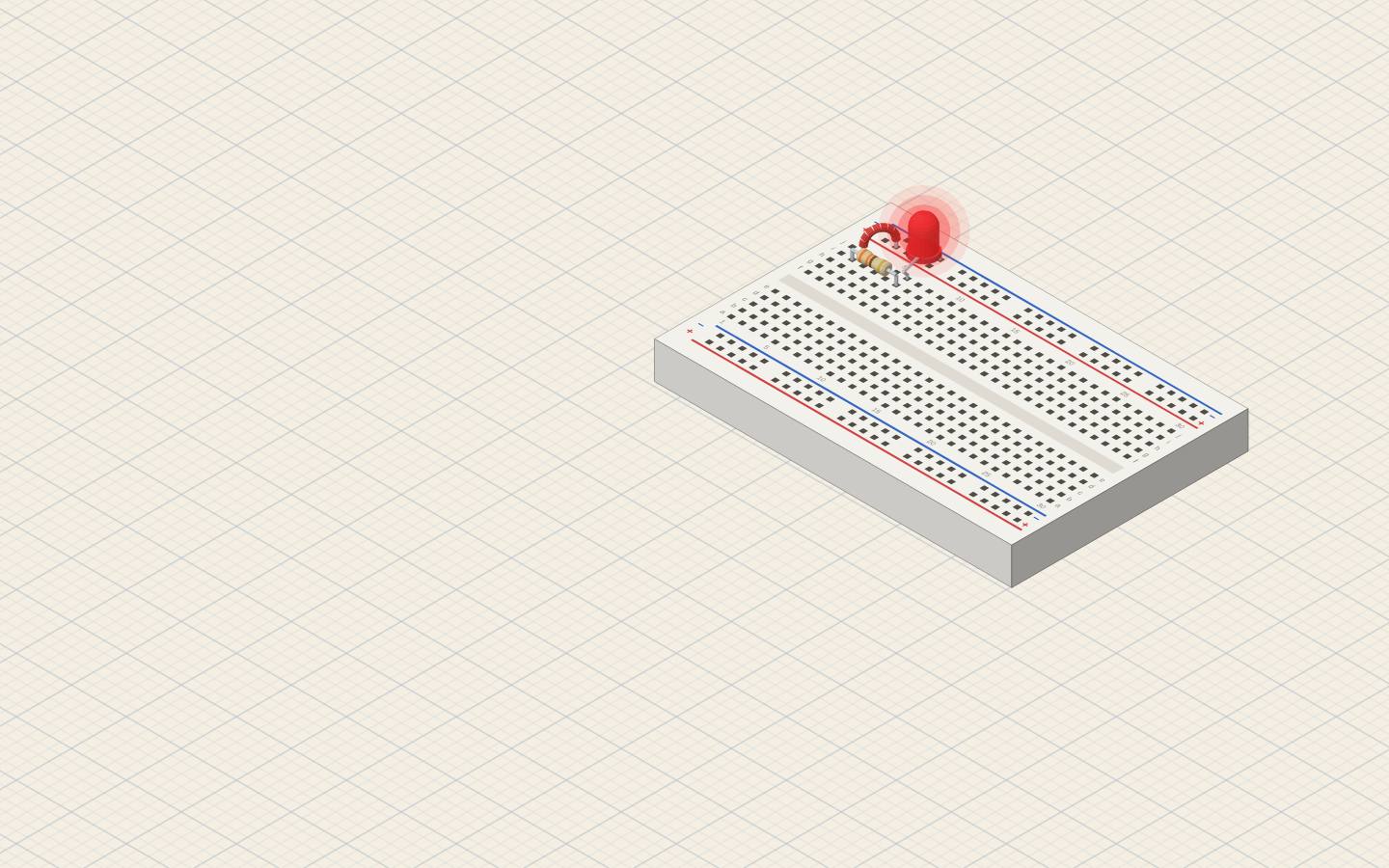
LED with a series resistorThe resistor sets the LED current: I = (V − Vf) / R
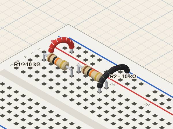
Voltage dividerVout = Vin · R2 / (R1 + R2), measured where the two resistors meet
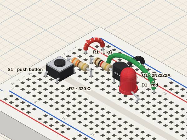
NPN transistor switchA small base current switches a larger collector current (press S1)
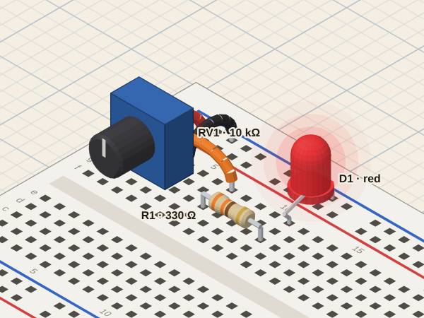
Potentiometer dimming an LEDThe wiper is an adjustable divider: its voltage goes from 0 to the supply
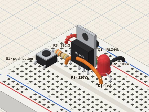
MOSFET switchThe gate takes voltage, not current; the pull-down R2 discharges it when S1 is released
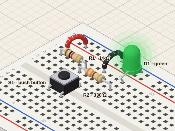
Button with a pull-up resistorReleased, R1 pulls the output up (LED on); pressed, S1 takes it to ground (LED off)
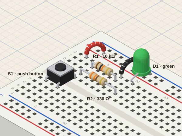
Button with a pull-down resistorReleased, R1 holds the output at ground (LED off); pressed, S1 takes it to the supply (LED on)
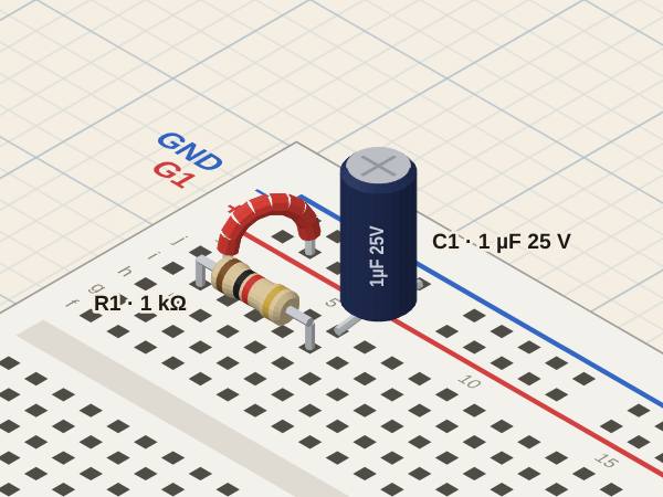
RC circuit with a square waveC1 charges and discharges with τ = R·C; compare it with the period of G1
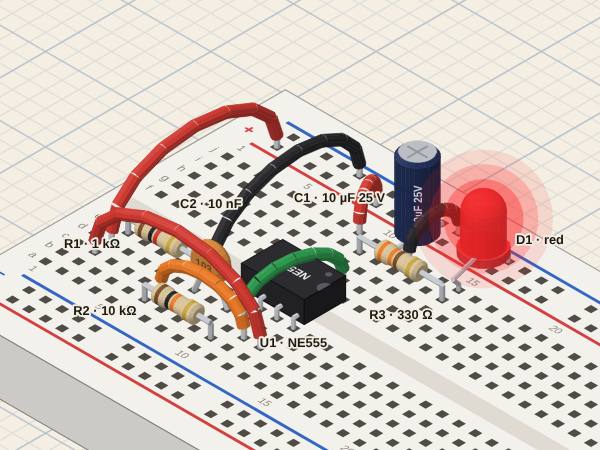
555 astable blinking an LEDC1 charges through R1 + R2 and discharges through R2: f ≈ 1.44 / ((R1 + 2·R2) · C1)
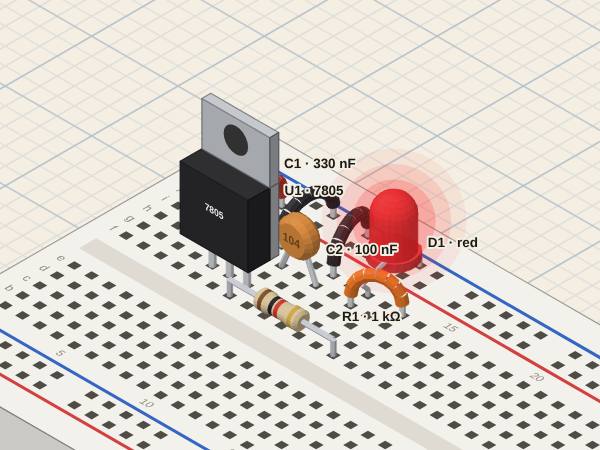
7805 regulator with a pilot LEDA fixed output from a higher input; the difference is lost as heat in U1
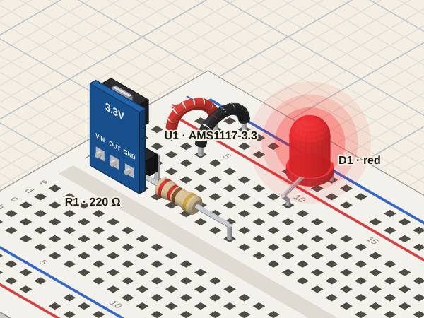
AMS1117 module with an LEDA low-dropout regulator: 3.3 V out from 5 V in
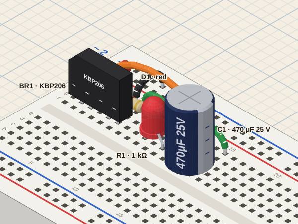
Bridge rectifier with a filter capacitorBoth half-waves come out positive; C1 fills the gaps between peaks (ripple)
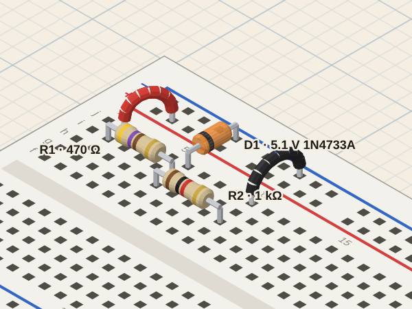
Zener regulatorReversed, the Zener holds its voltage; R1 takes the rest of the supply
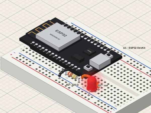
ESP32 blinking an LEDA GPIO pin as an output: digitalWrite(13, HIGH) lights D1, delay() sets the rhythm
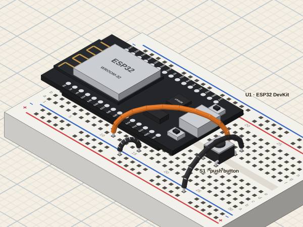
ESP32 reading a buttonA GPIO pin as an input with the internal pull-up: digitalRead(27) reads LOW while S1 is pressed
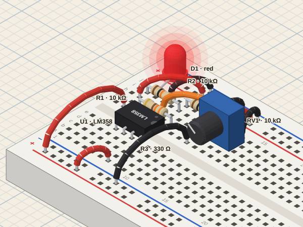
Op-amp comparatorWithout feedback the output saturates: high when V+ > V−, low when V+ < V−
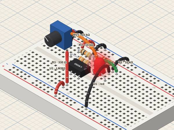
LM393 comparator (open collector)The output only pulls down: the LED, fed from the supply, lights while V− > V+
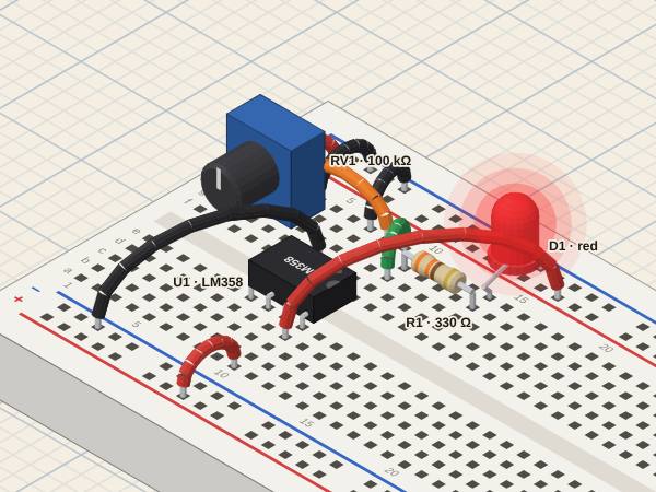
Op-amp voltage follower (buffer)With the output on V−, the output copies V+: the potentiometer gives a voltage, the op-amp gives the current
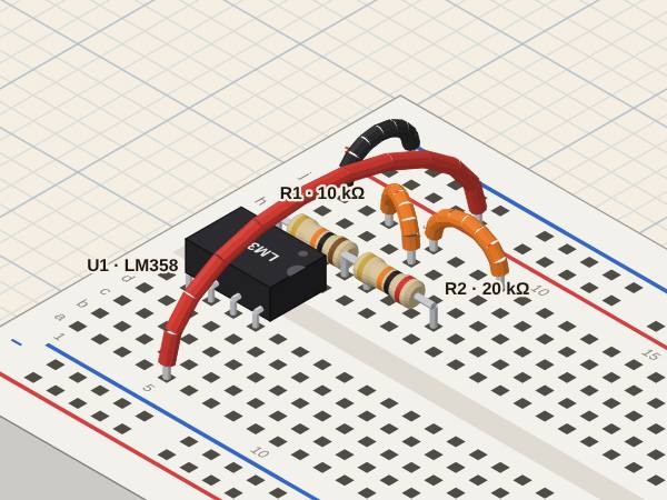
Non-inverting amplifierGain = 1 + R2/R1: the output is the input times 3, in phase
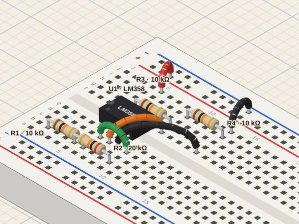
Inverting amplifierGain = −R2/R1 around the reference on V+: the output is twice the input, upside down
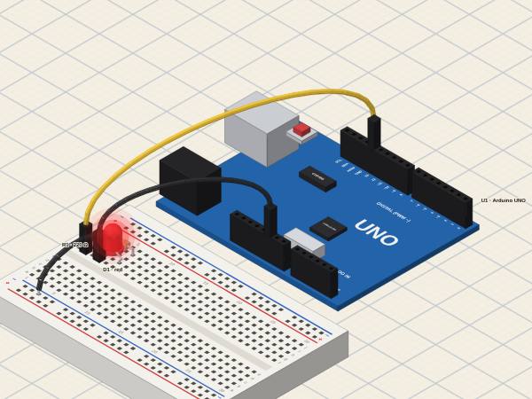
Arduino UNO blinking an LEDA pin as an output at 5 V: digitalWrite(13, HIGH) lights D1, delay() sets the rhythm
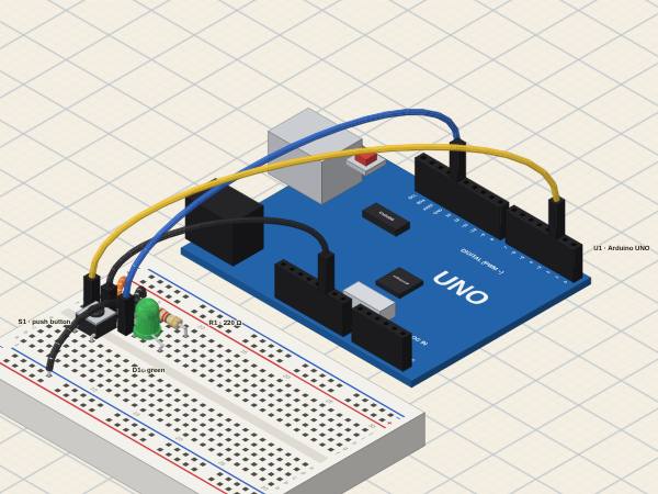
Arduino UNO: a button lights an LEDA pin as an input with the internal pull-up: it reads LOW while S1 is pressed, and the program decides the LED
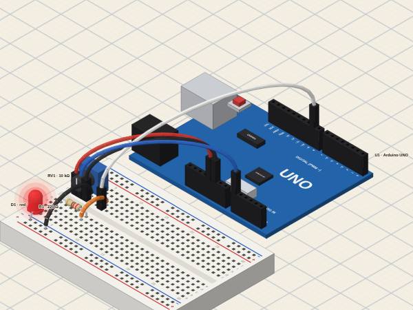
Arduino UNO: a potentiometer dims an LED (ADC and PWM)analogRead turns a voltage into 0…1023; analogWrite turns 0…255 into the share of time the pin is high
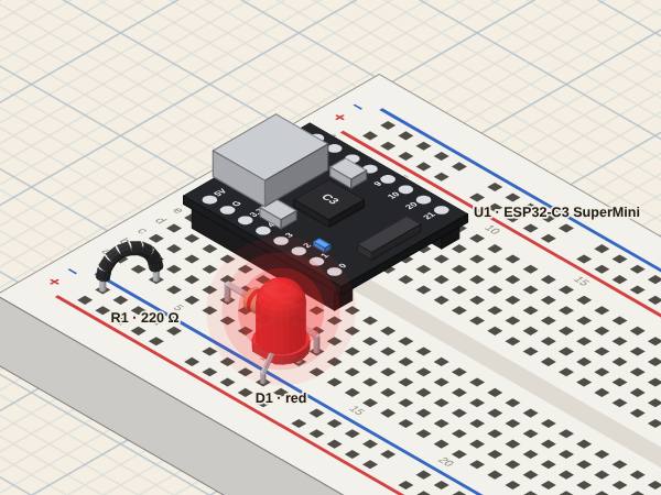
ESP32-C3 SuperMini blinking an LEDA GPIO as an output at 3.3 V: digitalWrite(3, HIGH) lights D1
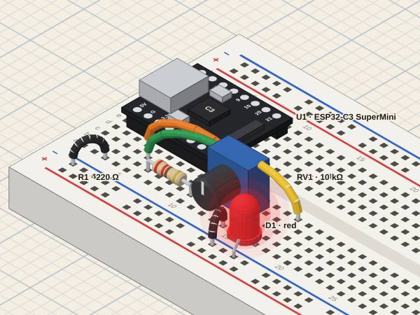
ESP32-C3: a potentiometer dims an LED (ADC and PWM)analogRead turns a voltage into 0…4095 (12 bits, up to about 2.5 V); analogWrite sets the share of time the pin is high
No circuits on this topic yet. Try «All».